Principles of Flight for Air Cadets

The article below is an extract from the Leading Cadet Resource Book. Please note this information is subject to Copyright 2018 Thomas Grocott. Not for reproduction. Thomas Grocott has asserted his right to be identified as author of this work in accordance with the Copyright, Designs and Patents Act 1988. All rights reserved.Some images in this publication are Crown Copyright and contain public sector information licensed under the Open Government Licence v3.0.
Principles of Flight
LO1: Understand the principles of flight.
• Identify factors that affect the creation of lift in an aircraft in flight.
• Describe how thrust, drag, weight and lift affect aircraft in flight.
LO2: Understand how the stability and manoeuvrability of an aeroplane are controlled.
• Explain how stability of an aeroplane is maintained.
• Explain factors which cause an aeroplane to stall.
• Explain how aeroplanes are designed to provide manoeuvrability.
• Describe how aircraft controls can be used for manoeuvrability.
LO3: Know the principles of flight and control for gliders.
• Identify forces acting on a glider in flight.
LO4: Know the principles of flight and control for rotary wing aircraft.
• Identify the features of rotary wing aircraft that enable flight and control.

When on water, the weight of a boat is supported by the water underneath it. Objects on land are similarly supported by the ground underneath them. Likewise, aircraft are supported by the air underneath them. But unlike the ground or the water, air can only support objects like aircraft if they are moving. If an aircraft stopped moving it would fall to the ground.
Newton’s Third Law
• In the 17th Century a scientist called Sir Isaac Newton worked out how things physically move, calling his findings the ’laws of motion’. His third law states that ’every action has an equal and opposite reaction’.
• For objects on the ground this means that no matter how heavy or light something is the ground supports it with a force that matches its weight. So an object weighing 100kg must be supported by a 100kg upward force from the ground. The same applies to something floating on the water; the water must support the weight of a floating object or it will sink.
• This is also true when in the air. To stay airborne the air must support the weight of the aircraft.
• Unlike objects on the ground or in the water (which can be supported when they are still), an aircraft must stay moving to keep it in the air.

Newton’s third law states that all objects must be supported with an equal force upward to keep them on the ground, water or air.
Airspeed and Air Pressure
• When you pick up an object you use your muscles to lift it off the ground. This generates and upward force that is called lift. The more force you use on pushing up the object the quicker it is lifted up.
• When an aircraft is in the air it is the air that ‘pushes’ it up. This is because the speed and pressure of air changes when travelling over a wing.
• This movement of air can be illustrated using a wind tunnel that becomes narrower in the middle:

• Air is represented by blue lines on the diagram. Speed and pressure of the air is measured at points A, B and C.
• As there is no way air can be stored in the wind tunnel, the amount of air stays the same.
• The airspeed and air pressure changes as it travels along the tunnel:
POINTS A > B - Airspeed increases to fit through the gap. Air Pressure decreases.
POINT B - Airspeed is at its maximum. Air pressure is at its lowest.
POINTS B > C - Airspeed decreases and air pressure increases to the levels seen at point A.
• The wind tunnel experiment shows us that as the speed of a smooth stream of air increases the pressure of it drops.
• It also shows that as airspeed decreases, pressure increases.
• This was first discovered by a scientist called Daniel Bernoulli who noticed the relationship between speed and pressure in water. Other scientists later discovered that it also applied to the air. Bernoulli called the effect ‘Bernoulli’s principle’.
Producing Lift
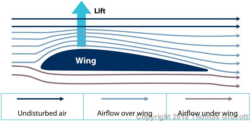
• Bernoulli’s principle states that when airspeed increases, air pressure decreases. The wings on an aircraft are specially shaped to take advantage of this.
• The air travels faster along the top of the wing when an aircraft is level or gaining height. This is because the undisturbed air just above the wing creates a narrowing which the air must travel more quickly through. This lowers the air pressure above the wing.
• This means the higher air pressure under the wing pushes it up, producing lift and supporting the aircraft in the sky.
Summary
• For every action, there must be an equal and opposite reaction.
• Aircraft can only be supported by the air if it is moving.
• When air has to travel through a tighter gap, its pressure decreases and speed increases.
• A wing generates lift because air travels over the top of it more quickly than underneath. This causes a drop in pressure over the top of the wing. The higher pressure air underneath it the wing pushes it up, producing lift and supporting the aircraft in the sky.

The speed of an aircraft, the shape and area of a wing, the density of the air, and angle of a wing all affect how much lift is produced. Different wing types have been designed to suit different types of aircraft. Flaps can also change the shape of a wing to increase or decrease the lift the wing generates.
Downwash
• Wings are often not parallel to the ground. They are angled slightly so the rear of the wing is lower than the front of it, as the diagram below shows.
• This deflects airflow on the rear of the wing slightly, creating an upward force which adds to the lift already produced.

Distribution of Lift
• Lift is not evenly distributed all over a wing. On a general purpose wing themost lift occurs on the top surface, nearest the front edge. This is where it is the most curved and where the air pressure is at its lowest and airspeed is at its highest.
• Any lift is generated at 90° to the airflow.
• The place where the average amount of lift is generated on a wing is called the centre of pressure. This is where all forces on the wing balance.
• The location of this centre of pressure changes depending on the angle of the wing relative to the ground and moves forward as this increases.
• The centre of pressure is similar to the centre of gravity for things on the ground. Try balancing a ruler on one of your fingers. The centre of gravity is the point where all forces are even and the ruler stays balanced on top of your finger.
Airspeed
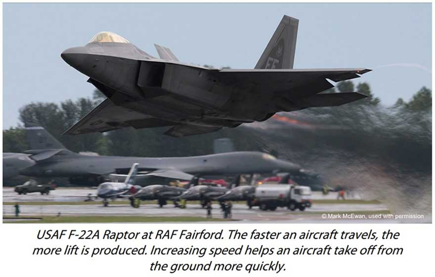
• Put simply, the faster an aircraft travels the more lift is produced. The speed that an aircraft travels is called its airspeed.
• To increase airspeed in flight you can increase the throttle or drop the nose of the aircraft.
• To reduce airspeed pitch up the nose so the aircraft climbs or reduce the throttle.
• Lift increases to the square of speed. So doubling the speed would produce 4 times as much lift!
Air Density
• As air becomes thinner it can’t provide as much lift. This becomes a problem on airfields located on high ground.
• Because of the reduced lift an aircraft needs to increase its normal take-off airspeed to get off the ground, therefore a longer than normal runway is required.
• Air temperature, wind speed, wind direction, the weight of an aircraft and length of runway can all have an influence on the decision on how to take off. This is especially true where the air is less dense. Sometimes pilots make the decision to wait until conditions improve before taking off.
Angle of Attack
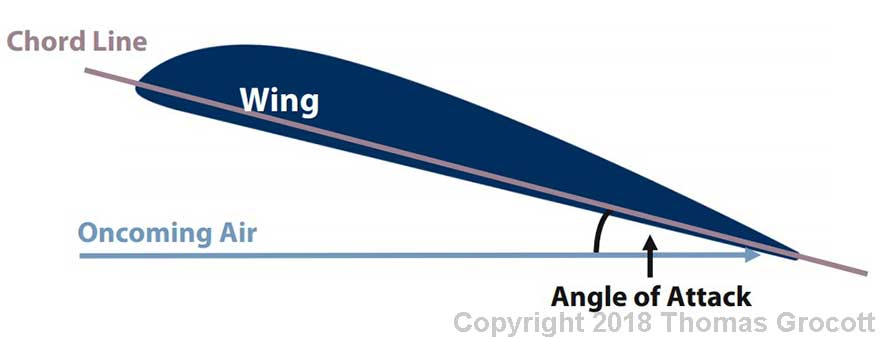
• The chord line is an imaginary line from the centre of the front (leading) edge to the centre of the back (trailing) edge of a wing.
• Wings are usually slightly angled against oncoming air. The difference between the chord line of the wing and the direction of oncoming air is called the angle of attack.
• On a general purpose wing as the angle of attack increases so does the lift, if airflow is kept constant.
• When the angle of attack reaches around 15° or more lift decreases rapidly and the aircraft stalls.
The Shape and Area of a Wing
• The chord line divides a wing into upper and lower sections.
• We can calculate the points halfway between the upper and lower surfaces of the wing. This gives us a curved line called the mean camber line. The larger the curve of this line, the more lift is produced.
• A more curved wing is said to have more camber than a less-curved wing.
• To improve the performance of particularly fast or large aircraft different wing shapes have been developed:

This shape is best suited for general aircraft travelling slower than the speed of sound. It generates moderate levels of lift. The size of the wing can change based on the aircraft’s size and weight.

This wing shape is good for larger, heavier aircraft that can only take off at slower speeds, as it has a deeper camber that produces more lift. This wing is not very stable at higher speeds.
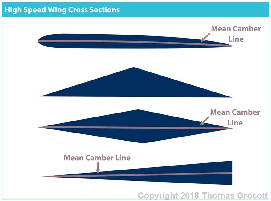
These wings are stable when travelling above the speed of sound, so they are more suitable for high speed aircraft. But the lack of camber means that less lift is produced so aircraft with this type of wing have to take off and land at higher speeds than aircraft with a general or high lift wing.
Flaps
• Flaps can change the shape of a wing, increasing its camber. When the flap is lowered, lift increases.
• On larger aircraft, more advanced Fowler flaps increase the camber and area of the wing by sliding backwards and hinging behind the wing. The extra area increases lift even further.

A hinged flap increases the camber of the wing, increasing lift.
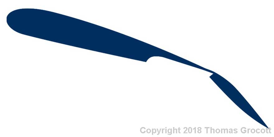
A Fowler flap increases the camber and area of the wing, increasing lift further than a hinged flap.
Summary
• The place where the average amount of lift is produced on a wing is called the centre of pressure.
• The faster an aircraft travels, the more lift is produced.
• As air becomes thinner lift is reduced. This can affect decisions on how to take off at higher altitudes.
• Different wing styles have been developed to suit different types of aircraft.
• Flaps can increase the camber of a wing to increase lift and/or add area to a wing.

Four forces act on an aircraft whilst it is in flight; lift, weight, thrust and drag. Most aircraft are designed to weigh as little as possible and are shaped to minimise drag. If these forces are too great they can make flying more difficult, or even impossible.
Lift and Weight
• If an aircraft is in straight and level flight the force lifting up the aircraft will be the same as the weight acting upon it. This means it stays at the same height. Remember, lift can only be generated when the aircraft is moving through the air.
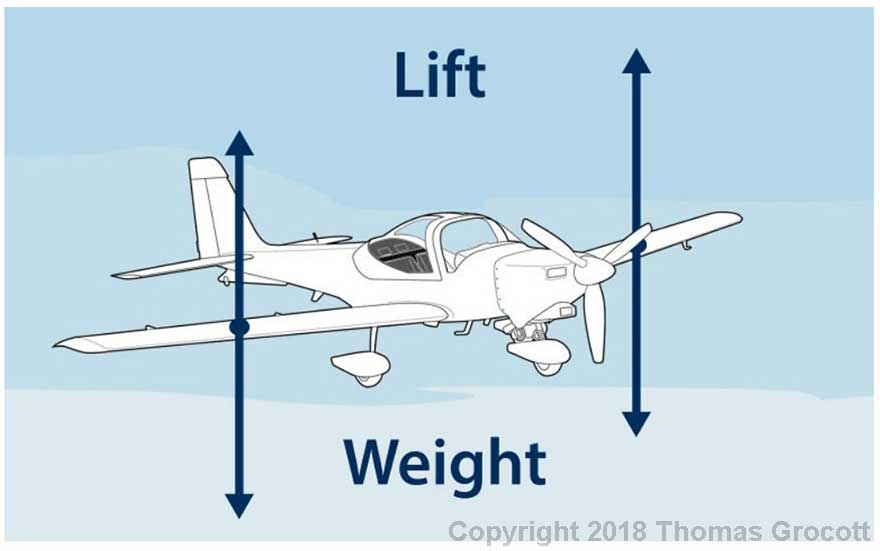
Lift is the same as the weight of the aircraft so it will stay level and not lose or gain any height.
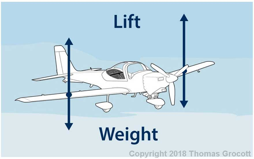
If the lift produced is greater than the weight of the aircraft, then it will climb upwards.
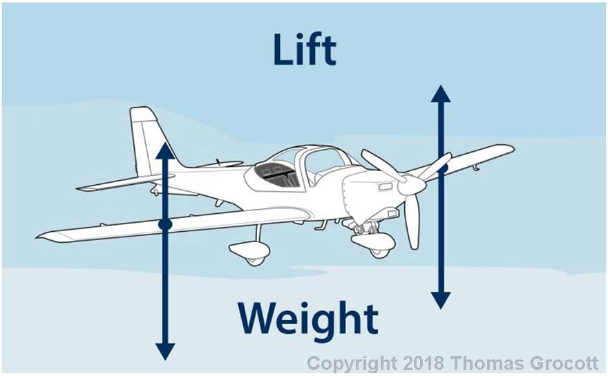
If the lift produced is less than the weight of the aircraft, then it will descend.
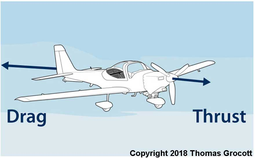
If drag is greater than thrust then the aircraft is slowing down.
Summary
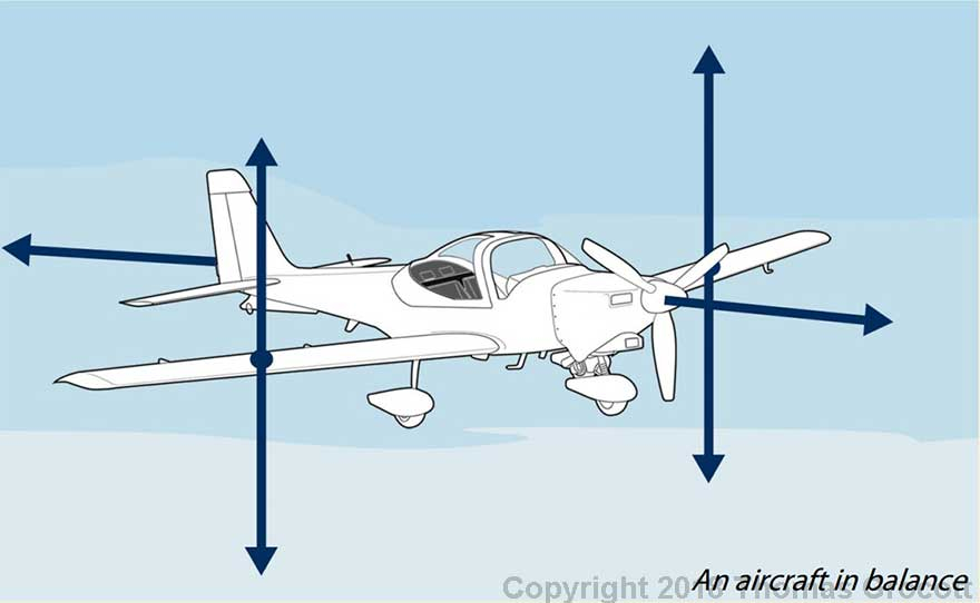
• Both lift and weight must be balanced to maintain the height of an aircraft.
• Both thrust and drag must be balanced to keep an aircraft travelling at a constant speed.
• All these forces work together to keep an aircraft straight and level in flight.
• Aircraft are designed to reduce weight and drag.

An aircraft moves along three axes. When an aircraft is disturbed from being in straight and level flight it will normally try to level itself without the pilot needing to make adjustments to the controls. This is called stability.
The Axes of an Aircraft
• There are three axes that an aircraft rotates around. They all pass through the centre of gravity, which is normally close to the centre of the aircraft.
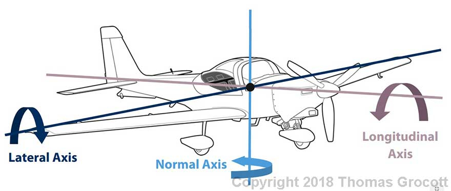
Lateral Axis - The axis in which the aircraft pitches up and down.
Normal Axis - The axis in which the aircraft yaws from side to side.
Longitudinal Axis - The axis in which the aircraft rolls from left to right.
• When an aircraft performs a manoeuvre on any of these axes it will normally return to straight and level flight without the pilot having to do anything.
• Most aircraft will return to straight and level flight by themselves if they encounter unstable air, like turbulence. These aircraft are said to have positive stability.
• Some aircraft, like high performance fighter jets do not do this automatically and the pilot must make corrections themselves. These aircraft are said to have neutral stability or negative stability.
Static Stability
• Static stability is how an aircraft reacts initially to a disturbance or an external force. There are three types of static stability:
Positive Static Stability - This type of aircraft will return to its original position (its attitude) when disturbed, without input from a pilot. After a disturbance the aircraft will correct itself.
Neutral Static Stability - These types of aircraft will stay in their new position after they have been disturbed. Without input from a pilot they will not return to their original attitude.
Negative Static Stability - These aircraft will continue to move away from their original attitude when disturbed. If this type of aircraft’s nose pitches down during a disturbance, it will continue to pitch down even more, resulting in the disturbance getting worse over time. This type of stability makes high-performance fighter jets more manoeuvrable, but is very undesirable for most other aircraft.
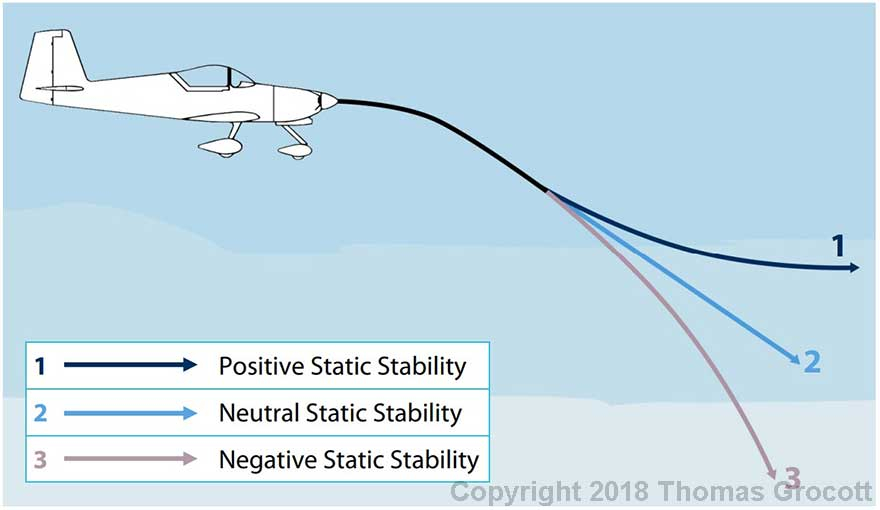
After a disturbance that causes this aircraft’s nose to pitch down, it could respond in three ways, depending on how stable it is.
Dynamic Stability
• After a disturbance or an external force an aircraft will need time to recover. Dynamic stability is how an aircraft reacts to these forces over time.
• Just like static stability, an aircraft can have positive, neutral and negative dynamic stability.
• For example, if some turbulence pitched the nose of an aircraft up it would first pitch down and the aircraft would start to descend before pitching back up again, a bit like a wave. The stability of the aircraft depends on what happens next.
Positive Dynamic Stability - These aircraft pitch up and down after a disturbance, but over time the up and down movements become smaller and smaller until the aircraft returns to straight and level flight.

Neutral Dynamic Stability - This type of aircraft continues pitching up and down after a disturbance. The waves do not dampen out over time or get any worse. Without any input from the pilot (or the aircraft’s computer) the aircraft would carry on doing this indefinitely.

Negative Dynamic Stability - When an aircraft has negative dynamic stability the up and down pitching movements will get worse over time making the aircraft unstable and without any intervention, dangerous to fly. These type of aircraft will almost always have computers installed to correct this when necessary.

Why Are Some Aircraft Unstable?
• Most aircraft are designed to be stable so that they are easier to fly. However, this makes them less manoeuvrable, especially at high speed.
• Some aircraft, like fighter jets, are designed to be unstable so that they are more manoeuvrable. This makes them easier to pitch, roll and yaw quickly and aggressively.
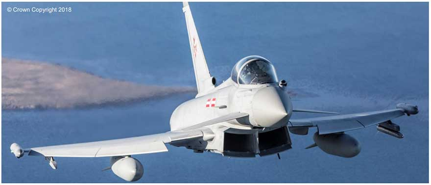
Fast jet aircraft like this Typhoon FGR4 are designed to be statically and dynamically unstable, making them more manoeuvrable.
• An aircraft needs to be stable along all three of its axes. The next section describes how an aircraft can be stable along its lateral, longitudinal and normal axes.
Longitudinal Stability
• Longitudinal stability is the stability of an aircraft in the pitching plane, along the aircraft’s lateral axis.
• To pitch the aircraft up or down the pilot moves the control column backwards or forwards. If the aircraft is longitudinally stable it will return to level flight if the control column is released.
• This is due to the shape of the tailplane of the aircraft. Whilst the aircraft is in straight and level flight it produces no lift.
• If the nose is pitched up, the rear of the aircraft is pitched down. This changes the angle of attack on the tailplane so it now produces lift. This pushes the rear of the aircraft back up to straight and level flight.
• Conversely, if the nose is pointing down then the rear of the aircraft is pitched up. In this situation the tailplane produces a downward force that pushes the rear of the aircraft back down to straight and level flight.
• Some aerobatic and combat aircraft are not longitudinally stable. This increases their manoeuvrability but makes them more difficult to fly.
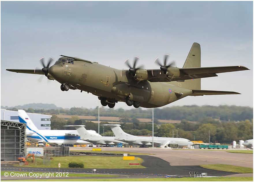
A Hercules at RAF Brize Norton, pitching its nose up during take-off. The tailplane of this aircraft helps to keep it longitudinally stable.
Lateral Stability
• Lateral stability is the stability of an aircraft in the rolling plane, along the aircraft’s longitudinal axis.
• To roll the aircraft left or right the pilot moves the control column left or right. If the aircraft is laterally stable it will return to level flight if the control column is let go.
• This is due to the positioning of the wings on the aircraft. Most aircraft have wings that are angled up slightly from horizontal. The angle between the wing and horizontal is know as the dihedral angle.
• Some aircraft only have a part of their wing angled upwards.
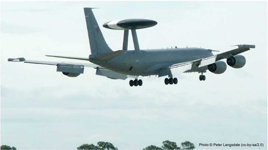
An E-3D Sentry taking off from RAF Waddington. The upward angle of the wings increase the aircraft’s lateral stability.
• If the aircraft rolls left then the left wing becomes lower than the right and the aircraft begins to slip, hitting a sidewind when it does.
• This causes the angle of attack on the wing to increase as it hits this sidewind at angle. This means the left wing produces more lift than the right wing and it begins to return back to its normal straight and level position.
• This also happens as an aircraft rolls right, but the forces act on opposite wings.
• Some aircraft have wings that are angled down. The angle between the wing and horizontal on these aircraft is called the anhedral angle. This causes something called lateral instability. This increases their manoeuvrability but makes them more difficult to fly.
Directional Stability
• Directional stability is the stability of an aircraft, in the yawing plane, along the aircraft’s normal axis.
• To yaw the aircraft left or right the pilot pushes on the left rudder pedal to yaw left or the right rudder pedal to yaw right. If the aircraft is directionally stable it will return to level flight if the rudder pedals are returned to their neutral position.
• This is due in part to the tail fin on the aircraft. If an aircraft yaws to the left or right, anything rear to the centre of gravity of the aircraft will generate a sideways force which will pull the aircraft back to its original path. Most aircraft will have a tail fin placed as far back as possible to help with this.
• Generally, the further back the centre of gravity is on the aircraft the larger the tail fin.
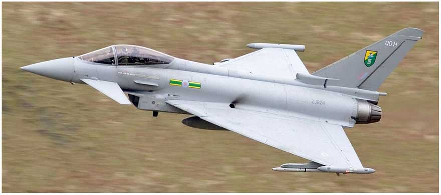
A Eurofighter Typhoon practicing manoeuvres in North Wales. The Typhoon’s large tail fin increases its directional stability
Summary
• Aircraft fly on three axes, the lateral axis (pitch), the normal axis (yaw) and the longitudinal axis (roll).
• Longitudinal stability is the stability of an aircraft in the pitching plane, along the aircraft’s lateral axis.
• Lateral stability is the stability of an aircraft in the rolling plane, along the aircraft’s longitudinal axis.
• Directional stability is the stability of an aircraft in the yawing plane, along the aircraft’s normal axis.
• Some aircraft decrease their stability deliberately in order to increase manoeuvrability.

When an aircraft’s wings cannot generate enough lift to stay in the air the aircraft is said to have stalled. Different types of aircraft will stall at different angles and speeds. However, this always occurs when the angle of attack on a wing becomes too great.
What is a Stall?
• We have already looked at a wing’s angle of attack. As the angle of attack increases the lift generated also increases up to a certain point.
• Each aircraft is different, but when an angle of attack of around 15° is reached then the airflow around the wing will change and it will no longer generate enough lift to stay in the air. This is because most of the lift around the wing is lost. This is known as the stall.
• A pilot must practice deliberately stalling their aircraft, so that they would know what to do if it there is an emergency. Aircraft are at greatest risk of stalling during take off and landing when an aircraft is likely to be travelling at a lower speed.
Stalling Angle
• The stalling angle of an aircraft varies and pilots will know what the stalling angle is for the particular aircraft they are flying.
• This angle depends on the type, shape, and size of the wing. It is normally around 15° for general purpose aircraft.
• The wing will always stall when the aircraft reaches that critical angle.
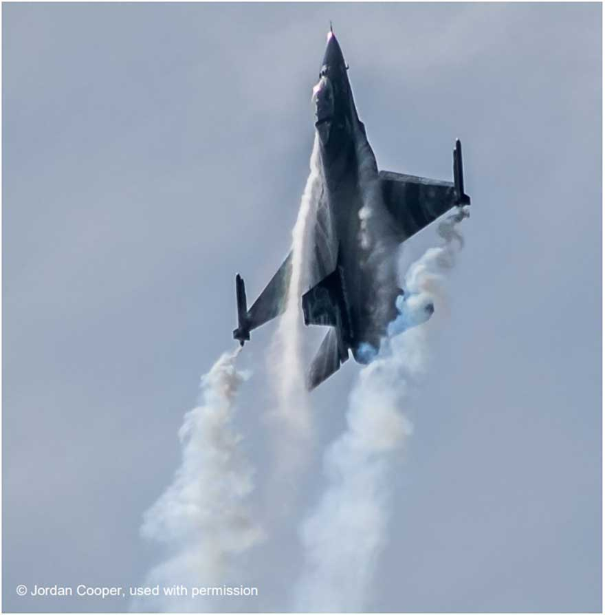
When a wing reaches an angle of attack greater than about 15°, the aircraft will stall.
Stalling Speed
• As speed decreases the angle of attack on a wing must increase to keep lift constant. As described earlier, when this angle gets above the stalling angle of the aircraft wing, the aircraft will stall.
• Each type of aircraft will have it’s own set of stalling speeds which can vary depending on flight conditions. Every aircraft will have an accompanying pilot’s notes booklet which gives information about the stalling speeds for that aircraft.
• The lower the stalling speed of an aircraft, the slower it can travel through the air.
• The stalling speed of an aircraft can change, with various factors influencing this:
Weight - As an aircraft gets heavier, more lift is needed to keep it airborne. So an aircraft full of cargo with a full fuel tank would be heavier than one with an empty hold and low fuel. The same fully loaded aircraft will have a higher stalling speed than if it is less full.
Ice and Dirt - Ice and dirt on a wing can change the wing’s aerodynamic shape, reducing lift. This will increase the aircraft’s stalling speed. The same can happen on a propeller as less thrust would be produced, which will also increase the stall speed.
Wing Damage - Just like ice and dirt, damage can change the shape of a wing, reducing the lift on it and thereby increasing the stall speed.
Power - The thrust produced by an aircraft’s engine can lower the stalling speed. Although the engine mostly produces thrust it can also generate a small amount of lift.
Flaps - Lowering flaps increases the curve of the wing and improves their shape for low speed flight. This reduces the stalling speed.
Turning the Aircraft - When an aircraft turns the lift force is no longer vertical. Only part of the wing can support the aircraft’s weight so stall speed is increased. The steeper the turn, the bigger the increase.

Once in the air an aeroplane is often stable enough to fly straight and level on its own. However, to do anything else a pilot needs to control the aircraft. Powered aircraft have controls and surfaces which enable a pilot to do just that.
Aircraft Controls
• Most powered aircraft have three main control surfaces that enable the pilot to control the aeroplane - the ailerons, elevators and rudders.
• The aircraft’s movements centre around three different axes. Look at the ‘Stability of an Aeroplane’ section for more information about this.
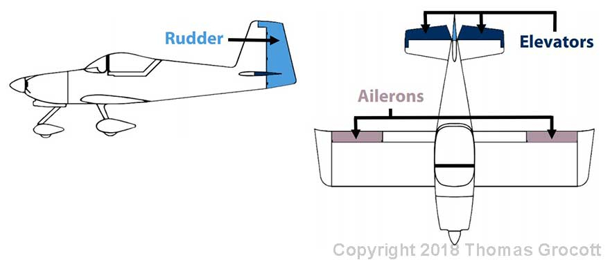
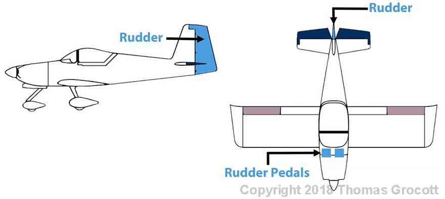
Rudder - Controls Yaw To a person sat in the aircraft this will look like the nose is moving left or right. Achieved by moving the rudder pedals forward and back. Aircraft turns on the normal axis.
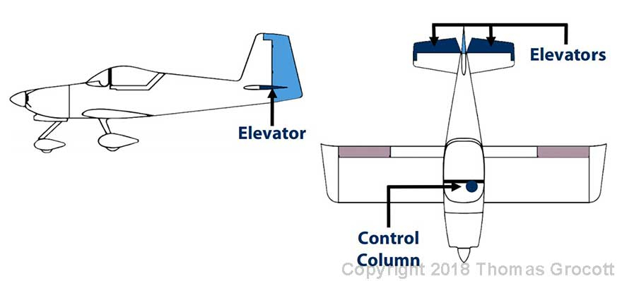
Elevators - Control Pitch To a person sat in the aircraft this will look like the nose is moving up and down. Achieved by moving the control column forward and back. Aircraft turns on the lateral axis.
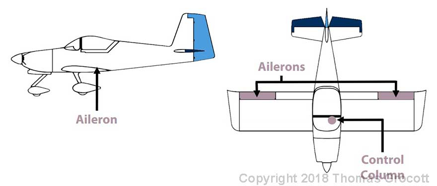
Ailerons - Control Roll To a person sat in the aircraft this will look like one wing is moving up whilst the other moves down. Achieved by moving the control column left and right. Aircraft turns on the longitudinal axis.
• Aircraft movements are always described in relation to what the pilot sees and not what the aircraft looks like to someone outside of it.
Yawing an Aircraft
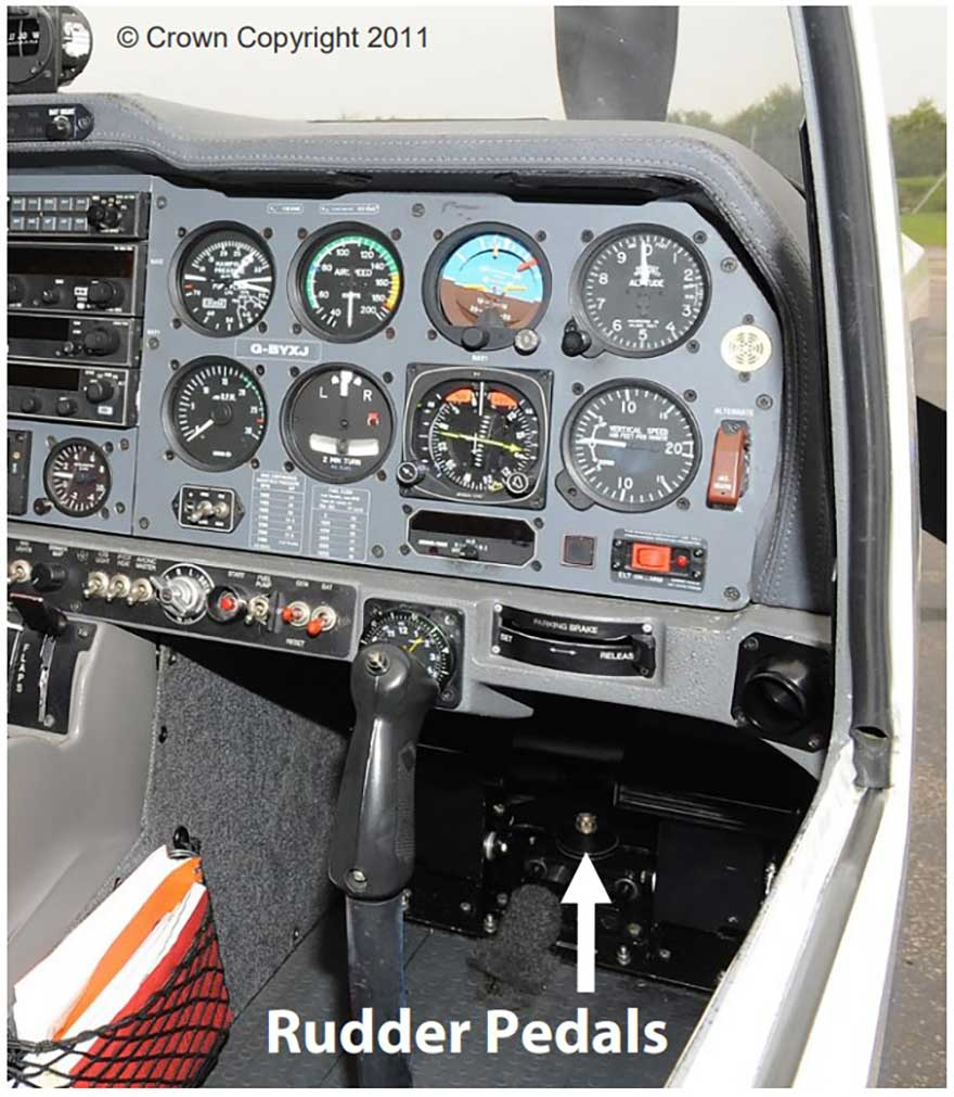
The cockpit of a Grob Tutor aircraft. The rudder pedals are located in the footwell.
• An aircraft is said to yaw when the aircraft’s nose is pushed left or right, moving the aircraft in the yawing plane, along the normal axis.
• To perform a yaw the pilot uses two rudder pedals which are found in the footwell of the cockpit. When an aircraft is in flight the pilot normally keeps his feet rested on these pedals.
• On most aeroplanes the pedals control a fin called the rudder, which is on the aircraft’s tail. When the left rudder pedal is pressed forward the rudder moves left. This pushes the tail sideways to the right, causing the nose to turn left.
• This movement stops when the pilot lets go of the pedals and the rudder returns to its normal position.
• The opposite happens then the pilot pushes the right rudder pedal forward. The rudder moves right, pushing the tail to the left, causing the nose to turn right.
• So, to yaw the aircraft left the pilot presses the left rudder pedal. To yaw the aircraft right, the pilot presses the right rudder pedal.
Pitching an Aircraft
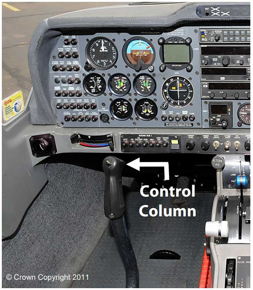
The cockpit of a Grob Tutor aircraft. The control column is just in front of the pilot
• An aircraft is said to pitch when the nose moves up and down, moving the aircraft in the pitching plane, along the lateral axis.
• To pitch the aircraft the pilot uses the control column, which is found just in front of their seat.
• When the pilot pushes the control column forward the elevators lower. These are normally found on the back of the tailplane.
• This increases the tailplanes angle of attack, therefore increasing the lift on the rear of the aircraft. Doing this pushes down the nose of the aircraft, causing the aircraft to dive.
• When the pilot pulls the control column back towards him the opposite occurs. Lift is reduced on the tailplane, which pushes the rear of the aircraft down, thereby pushing the nose of the aircraft up, causing the aircraft to climb.
• When the pilot lets go of the control column the tailplane goes back to its normal position and the aircraft will normally return to straight and level flight.
Rolling an Aircraft
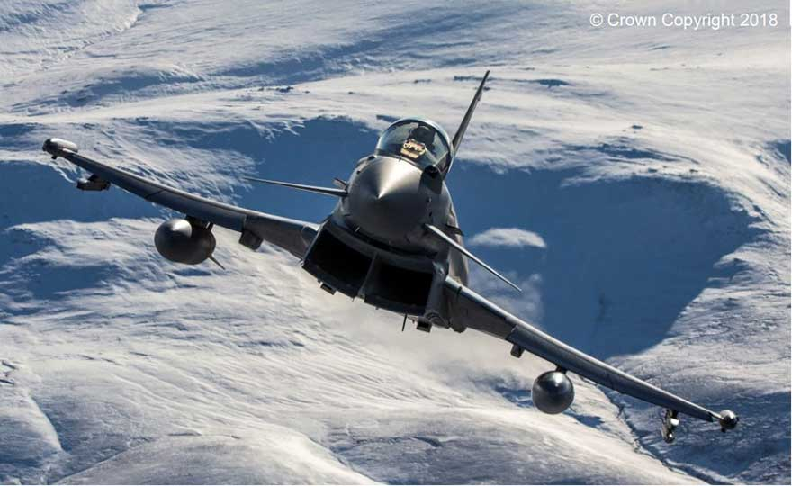
An RAF Typhoon aircraft pitching and rolling over West Falkland Island.
• An aircraft is said to roll when one wing moves up and the other moves down, causing the aircraft to move in the rolling plane, along the longitudinal axis.
• To roll the aircraft the pilot uses the control column, which is located just in front of their seat.
• This movement of the control column controls the ailerons, which are located on the rear of each wing, often near the wingtip.
• When the pilot moves the control column to the left the left aileron rises and the right one is pushed down. This decreases the angle of attack on the left wing and it produces less lift. The opposite occurs on the right wing as its angle of attack increases and it produces more lift.
• The aircraft will continue to roll until the pilot returns the control column back to the centre.
• When the pilot moves the control column to the right the opposite occurs. More lift is produced on the left wing and less lift is produced on the right. This causes the aircraft to roll right.
Trimming Tabs
• In normal conditions most aircraft can fly straight and level with minimal input on the controls from the pilot. If this wasn’t the case then the aircraft would become much more difficult to fly, as the pilot would need to make constant adjustments to keep the aircraft flying straight and level.
• Sometimes the weight of an aircraft may change whilst in flight (when fuel is used up etc) or weight could be moved around the aircraft. The centre of pressure on the wing will also change during flight.
• This can affect the balance of forces on the aircraft, putting the aircraft out of balance. This makes the aircraft harder to control.
• To combat this problem, most aircraft have trimming tabs located around the aircraft. These help cancel out the forces which may cause the aircraft to become unstable.
• The trimming tabs are normally controlled by trimming wheels found on the inside of the aircraft. Turning them adjusts the trimming tabs on the outside of the aircraft, correcting the unstable forces.
• Trimming tabs are found on each control surface in most aircraft. They work by holding the control column or rudder in a fixed position, removing the need for the pilot to do this manually.


