Aircraft Shapes and Materials
The shape of the aircraft since their first flight in December 1903 has changed dramatically from the light wooden framed, linen covered, bi-plane of the Wright Brothers to the gleaming Mach 2+ swept delta and variable geometry aircraft of the 21st Century.
The biplane was light and slow with a short wing span but a large wing area and therefore great maneuverability. The strut and bracing wires between the wings provided a light but strong structure having a low wing loading and hence a safe, low landing speed without resorting to complex flaps and slats arrangement to help generate low speed lift. Unfortunately the early biplane airframes were inefficient at speeds in excess of 150mph, and ultimately replaced by the monoplane.
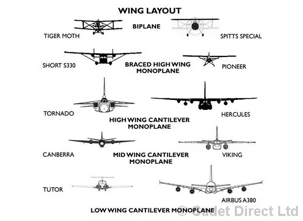
The monoplane can have a braced or a cantilever (i.e. supported at one end only) type of wing which can be placed high, middle or low on the fuselage.
Because of the need for greater speed, the monoplane became more complicated and therefore more expensive to build. It required retractable undercarriages, the piston engine was replaced by a turbojet engine and a swept wing became a necessity, all of which increased the weight of the aircraft.
To overcome these problems, the efficiency of the aerofoil needed to be increased, and extra lift inducing devices were needed to be fitted.
Materials have changed significantly over the history of aviation - from the wood and linen construction of the early aircraft, to the light alloys of World War II, and then the steels, fiberglass, carbon fiber, titanium and composites of modern day aircraft. Because of the stresses and strains that are applied to an aircraft in flight, every safeguard is applied and all major components are “lifted” causing them to be replaced after a certain number of flying hours to ensure safety and to extend the life of the aircraft concerned.
Engine Installations
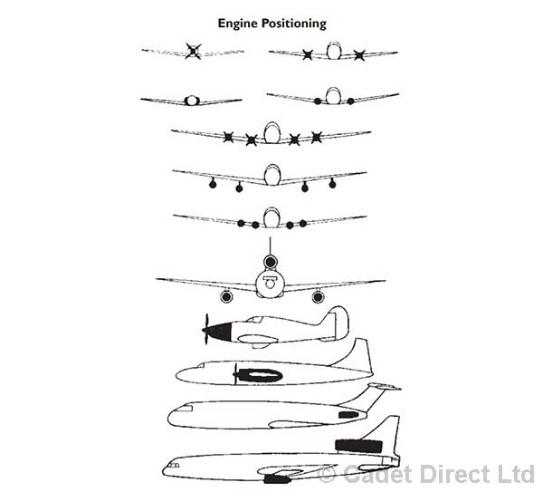
When considering where to put the engines on a new aircraft, the designer has to consider a number of factors:-
- a. What is the specific role of the aircraft?
- b. What are the performance requirements?
- c. How many engines are needed to meet the performance requirements?
- d. What engines are appropriate to meet these needs, and what are their size and weight?
- e. How and where will the engines be mounted? f. Will this be easy to remove for maintenance and engineering?
- g. How efficient is the engine - how much fuel will the aircraft need and where can it be stored?
- h. Will the engine(s) positioning affect the centre of gravity?
- i. Will the engine(s) positioning affect the directional stability of the aircraft?
These, as well as many other questions, will allow the designer to use the most appropriate engine, and in the right place on the aircraft. Engines can be fitted in the fuselage, outside the fuselage, inside the wings, on the wings or suspended under the wings in pods. In fact they can go in almost any place on an aircraft and have done so over the past 90 years.

Undercarriage
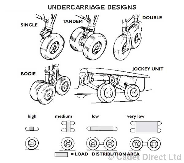
From the skids of early biplanes and gliders, the floats upon seaplanes and through the complex multi-wheeled, jockey units of modern cargo aircraft such as the AN225, undercarriages are an essential component of all aircraft. They are required to:-
- a. Support the aircraft when it is on the ground
- b. Keep the engines and sensitive components clear of any obstructions.
- c Absorb the shock of landing and provide reasonably smooth taxiing.
- d. Withstand side loads of crosswinds at takeoff and landing.
Modern aircraft tend to have main and nose wheel units and the number of wheels and type of undercarriage leg is dependent on the aircraft’s size and role.

Aircraft Controls
All aircraft have to be fitted with a system that will enable the pilot to control and manoeuvre the aircraft in flight. There are 3 main control surfaces:-
ELEVATORS on the Tailplane control the PITCH axis movement.
AILERONS on the Wing controls the ROLL axis movement.
RUDDER on the Fin controls the YAW axis movement.
Depending on an aircrafts shape and configuration some of these control surfaces can be merged - for example Tailerons, Elevons and variable incidence of tailplanes. Canards are another example of where the control surfaces has been moved and no longer fits the traditional aircraft shape - but they still do the job of a tailplane.
The aircraft's control surfaces are operated from the Control Column and Rudder Bar via a number of alternative systems.
- • Mechanical linkages - the control column is linked directly to the control surfaces by cables’, the Viking glider is an example of such systems, but it is also used in aircraft such as the Boeing 707.
- • Power assisted hydraulics - The pilot’s movement of a control causes the mechanical circuit to open the matching servo valves in the hydraulic circuit. The hydraulic circuit powers the actuators which then move the control surfaces. This arrangement is found in most jet transports and high performance aircraft. These include the Antonov An-225, the Lockheed SR-71 and most aircraft in-between.
- • Fly-by-wire: (FBW) electronic signals from the control column operate signal transducers which generate the appropriate commands and transmit them to controllers at the control surfaces. This reduces the need for heavy, complex and high maintenance hydraulic systems. An early form of this system was used in the Avro Vulcan. Modern aircraft which use it include Airbus 320 and the Boeing 777.
- • Fly-by-light: Fly-by-light or Fly-by-optics (FBL) is sometimes used instead of fly-by-wire because it can transfer data at higher speeds, and it is immune to electromagnetic interference. In most cases, the cables are just changed from electrical to fiber optic cables. The data generated by the software and interpreted by the controller remain the same.
As aircraft move towards FBW and FBL systems so the need for heavy mechanical circuits is removed The next step is to eliminate the bulky and heavy hydraulic circuits which move the control surfaces.
The absence of hydraulics greatly reduces maintenance costs, and also decreases the aircrafts overall weight. This system is used in the Lockheed Martin F-35 and in Airbus A380 backup flight controls.
Autopilot
Because of the distances that aircraft travel and the length of time they are in the air, aircrews need to be relieved of the mental and physical strain that occurs in controlling the aircraft. This is the primary function of the autopilot. It is a mechanism that, when switched on, can sense a disturbance of the control surfaces, the aircraft's attitude or heading, and apply immediate counter movements to maintain the course and height set by the pilot.
Aircraft Systems
Unlike a house, an aircraft is not connected to common services such as electricity, gas or mains water. Therefore each aircraft has to be independent and provide its own services. These cover all aspects of the aircraft’s working parts and the following are the major systems involved:
Hydraulics: are used for retractable undercarriages, flaps, bomb bays, wheel brakes etc
Pneumatics: (or compressed air) has similar uses to the hydraulic systems above, and for the use of control airflow to the wing surfaces to help in improving lift.
Electricals: Most aircraft flying today require electrical power and this is usually provided by a generator driven by the aircraft’s engine. AC and DC voltages of various frequencies are provided by Transformers, Rectifiers, Invertors or Frequency Changers. Typical systems requiring electrical power include radios, radar, instruments, actuators and a host of other systems.
Ice Protection: When flying in all weather conditions and at high altitudes ice can form on parts of the aircraft. This is particularly dangerous if it forms on the control surfaces or wing as it can change the shape of the aerofoil, so reducing lift, or stop the control surfaces from moving, so stopping the aircraft from changing its attitude. There are four systems employed to prevent ice collecting on an aircraft: Fluid, Mechanical, Thermal and Electrical.
Airspeed Indicator: This, as the name implies, gives the pilot his Indicated Air Speed (IAS). This is the speed of the aircraft relative to the air: which it is flowing over it. It is not the aircrafts ground speed - i.e. how fast it is travelling over the ground. IAS is obtained by measuring the air pressure caused by the aircraft’s movement.
Altimeter: This instrument gives the height of the aircraft above a certain reference point determined by a known barometric pressure. It measures the difference between the pressures of the free air surrounding the aircraft with-that of the reference point.
Artificial Horizon: By using a gyroscope rotating at very high speed, this instrument will indicate the natural horizon whatever the aircraft’s attitude in flight.
Compass: This is one of man’s oldest means of navigation. It will give the direction of magnetic north, regardless of the aircraft's attitude. Other navigation instruments will very between aircrafts. Some will rely on ground based equipment, whilst others are satellite based - for example an Instrument Landing System (ILS), Automatic Direction Finding (ADF), Distance Measure Equipment (DME) or a Global Positioning System (GPS).
Rate of climb and descent indicator: This instrument gives the pilot an indication of how fast they are descending or ascending.
Turn and slip indicator: This instrument shows the rate of turn. The rate of turn is indicated gyroscopically and the coordination of the turn is shown by an inclinometer, which works in a way similar to a simple pendulum. No pitch information is provided. The rate of turn is the actual rate at which the airplane is rotating.
Other Instruments: A number of other instruments may also be present. These will indicate engine information, include temperatures, engine revolutions, oil levels, pressures. These may also be fuel or battery information present.Other instruments may involve navigation aid, radio and communications.
You should not touch these unless you have been specifically told to do so by the pilot
Aircraft Instruments

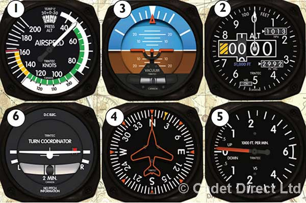
1. AIRSPEED INDICATOR - This, as its name implies, gives the pilot his Indicated Air Speed (IAS) which is the speed of the aircraft in relation to the air which is flowing over it and is not its speed over the ground. IAS is obtained by measuring the air pressure caused by the aircraft’s movement.
2. ALTIMETER - This instrument gives the height of the aircraft above a certain reference point determined by a known barometric pressure. It measures the difference between the pressure of the free air surrounding the aircraft and that of the reference point.
3. ARTIFICIAL HORIZON - By use of a gyroscope rotating at very high speed, this instrument will indicate the natural horizon what ever the attitude of the aircraft in flight.
4. COMPASS - This is one of man’s oldest means of navigating across the earth’s surface. It is therefore not surprising that an aircraft should have one. Other instruments used are aimed at navigation, communication and landing e.g. Instrument Landing System (ILS), Automatic Direction Finding (ADF), Distance measuring Equipment (DME) and in these days of computers and satellites, more and more of this type of electronic equipment is being used.
5. RATE OF CLIMB AND DESCENT - The rate of climb RoC is the speed at which an aircraft increases it's altitude.
6. TURN and SLIP INDICATOR - The TURN and SLIP INDICATOR shows the rate and direction of a turn. It tells the pilot if he is performing a coordinated turn using all his controls most efficiently


